
Thick-edged Grid
Circular Cross-Section
(Pipe Flow - Guide)

Model description:
This model of component calculates the minor head loss (pressure drop) generated by the flow in a thick-edged grid (perforated plate) installed in a straight pipe. Moreover, when the thickness of the grid is greater than 1.4 times the diameter of the equivalent section orifice of the holes, the head loss due to friction in the holes is also taken into account because it becomes significant.
The head loss by friction in the inlet and outlet piping is not taken into account in this component.
Model formulation:
Pipe cross-sectional area (m²):

Cross-sectional area of one hole (m²):

Clear cross-sectional area of the grid (m²):
![]()
Porosity:
![]()
Equivalent section orifice diameter (m):

Ratio between the diameters of the equivalent section orifice and the pipe:

Pipe velocity (m/s):
![]()
Holes velocity (m/s):

Mass flow rate (kg/s):
![]()
Reynolds number in pipe:
![]()
Reynolds number in holes:
![]()
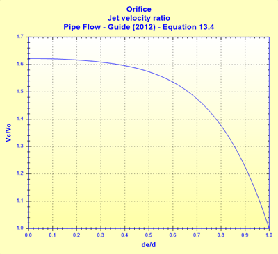
Jet velocity ratio:
![]() ([1]
equation 13.4)
([1]
equation 13.4)
Velocity in vena contracta:
![]()
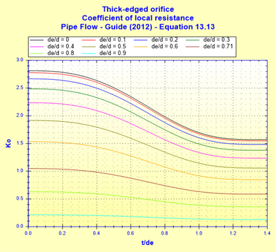
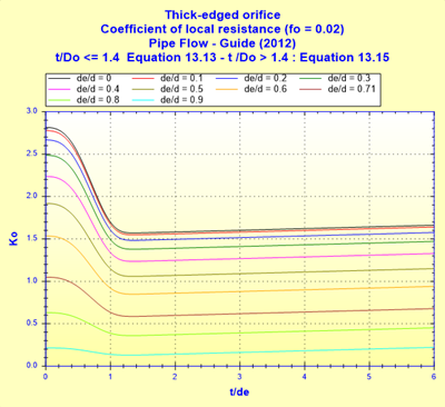
Coefficient of local resistance:
n Thickness to equivalent diameter ratio (t/de) £ 1.4:
 ([1] equation 13.13)
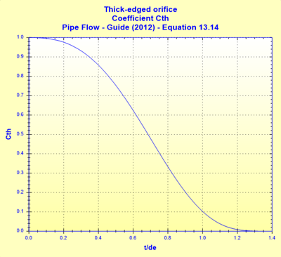
with:
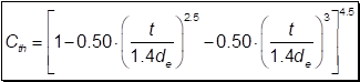 ([1] equation 13.14)
n Thickness to equivalent diameter ratio (t/de) > 1.4:
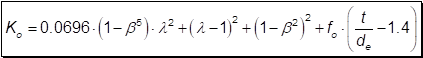 ([1] equation 13.15)
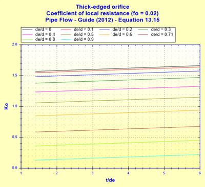 ([1] equation 13.15 with fo = 0.02)
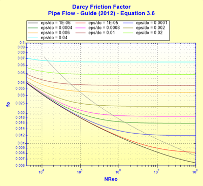
with:
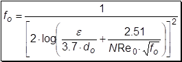 Colebrook-White
equation ([1] equation 3.6)
Colebrook-White
equation ([1] equation 3.6)
n All thickness to equivalent diameter ratios (t/de):
 ([1] equations
13.13 and 13.15
with fo = 0.02)
([1] equations
13.13 and 13.15
with fo = 0.02)
Total pressure loss coefficient (based on the mean pipe velocity):
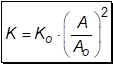
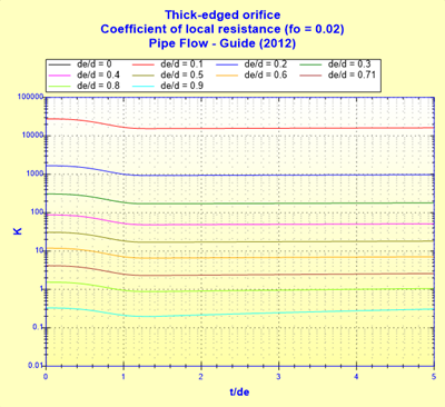 (with fo = 0.02)
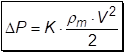
Total pressure loss (Pa):
Total head loss of fluid (m):
Hydraulic power loss (W):
![]()
Symbols, Definitions, SI Units:
d Internal pipe diameter (m)
A Pipe cross-sectional area (m²)
d0 Holes diameter (m)
ao Cross-sectional area of one hole (m²)
N Holes number ()
A0 Clear cross-sectional area of the grid (m²)
f Porosity ()
de Equivalent section orifice diameter (m)
b Ratio between the diameters of the equivalent section orifice and the pipe ()
Q Volume flow rate (m³/s)
G Mass flow rate (kg/s)
Vo Mean velocity in holes (m/s)
V Mean velocity in pipe (m/s)
NReo Reynolds number in holes ()
NRe Reynolds number in pipe ()
l Jet velocity ratio ()
Vc Mean velocity in vena contracta (m/s)
t Thickness grid (m)
Ko Coefficient of local resistance ()
Cth Coefficient ()
fo Darcy Friction factor ()
K Total pressure loss coefficient (based on the mean pipe velocity) ()
DP Total pressure loss (Pa)
DH Total head loss of fluid (m)
Wh Hydraulic power loss (W)
rm Fluid density (kg/m³)
n Fluid kinematic viscosity (m²/s)
g Gravitational acceleration (m/s²)
Validity range:
· turbulent flow regime in holes (NReo ³ 104)
· stabilized flow upstream of the grid
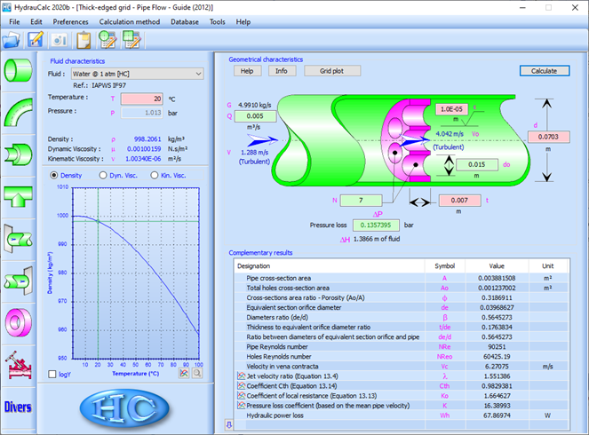
Example of application:
References:
[1] Pipe Flow: A Practical and Comprehensive Guide. Donald C. Rennels and Hobart M. Hudson. (2012)
HydrauCalc Edition: May 2020
© François Corre 2019-2020