
Round-Edged Grid
Circular Cross-Section
(IDELCHIK)

Model description:
This model of component calculates the minor head loss (pressure drop) generated by the flow in a round-edged grid (perforated plate) installed in a straight pipe.
The head loss by friction in the inlet and outlet piping is not taken into account in this component.
Model formulation:
Hydraulic diameter (m):
![]()
Pipe cross-section area (m²):

Cross-section area of one hole (m²):

Clear cross-sectional area of the grid (m²):
![]()
Mean velocity in pipe (m/s):

Mean velocity in holes (m/s):

Mass flow rate (kg/s):
![]()
Reynolds number in pipe:
![]()
Reynolds number in holes:
![]()
n Re0 ³ 105
with :
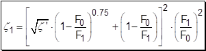
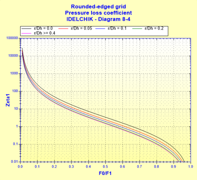
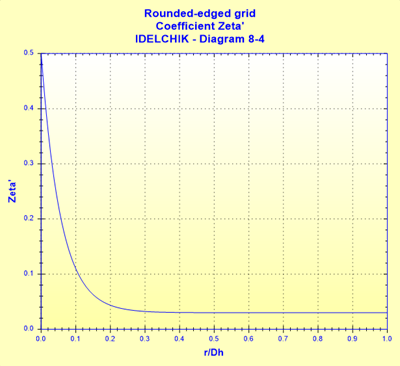
Coefficient of effect of the round:
![]() ([1] diagram 8-4)
([1] diagram 8-4)
n Re0 £ 105
Quadratic local resistance coefficient:
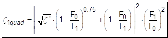 ([1] diagram 8-4)
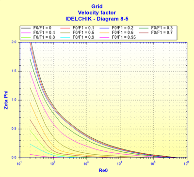
Velocity factor:
 ([1]
diagram 8-5)
([1]
diagram 8-5)
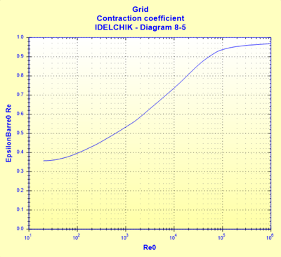
Contraction factor:
![]() ([1]
diagram 8-5)
([1]
diagram 8-5)
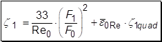
Coefficient of local resistance:
l 30 < Re0 < 105
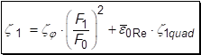 ([1] diagram 8-5)
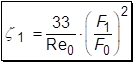
l 10 < Re0 £ 30
 ([1] diagram 8-5)
l Re0 £ 10
 ([1] diagram 8-5)
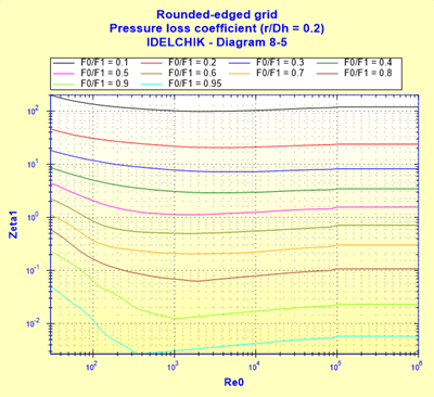 ([1] diagram 8-5
with r/Dh = 0.2)
([1] diagram 8-5
with r/Dh = 0.2)
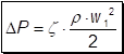
Pressure loss coefficient (based on the mean pipe velocity):
![]()
Total pressure loss (Pa):
Total head loss of fluid (m):

Hydraulic power loss (W):
![]()
Symbols, Definitions, SI Units:
Dh Hydraulic diameter (m)
D1 Pipe internal diameter (m)
F1 Pipe cross-sectional area (m²)
N Holes number ()
D0 Holes diameter (m)
F0 Clear cross-sectional area of the grid (m²)
f0 Cross-section area of one hole (m²)
Q Volume flow rate (m³/s)
w1 Mean velocity in pipe (m/s)
w0 Mean velocity in holes (m/s)
G Mass flow rate (kg/s)
r Radius of the round (m)
Re1 Reynolds number in pipe ()
Re0 Reynolds number in holes ()
z1quad Quadratic pressure loss coefficient determined as Re = 105 ()
zj Velocity factor ()
`e0Re Contraction factor ()
z1 Coefficient of local resistance ()
z Pressure loss coefficient (based on the mean pipe velocity) ()
DP Total pressure loss (Pa)
DH Total head loss of fluid (m)
Wh Hydraulic power loss (W)
r Fluid density (kg/m³)
n Fluid kinematic viscosity (m²/s)
g Gravitational acceleration (m/s²)
Validity range:
· any flow regime: laminar and turbulent
· stabilized flow upstream of the grid
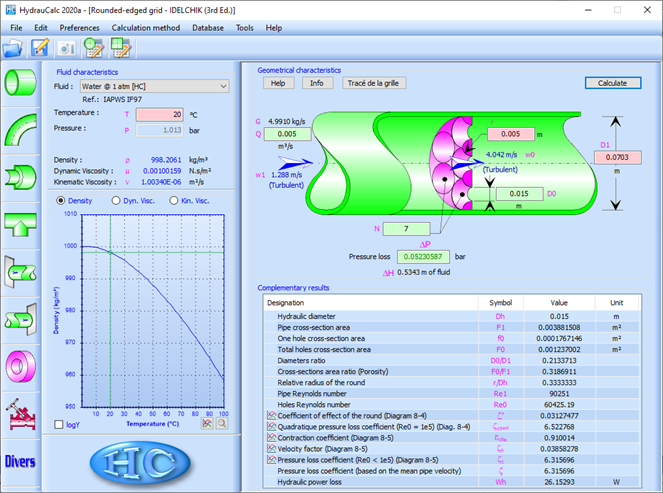
Example of application:
References:
[1] Handbook of Hydraulic Resistance, 3rd Edition, I.E. Idelchik
HydrauCalc Edition: May 2020
© François Corre 2019-2020