
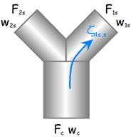
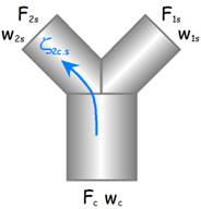
Symmetric dividing Y-junction with branches of unequal sections
Circular cross-section
(IDELCHIK)
Model description:
This model of component calculates the minor head loss (pressure drop) generated by the flow in a symmetric dividing Y-junction. For this component, the diameters of the right and left branches are equal, and the common branch area is equal to the sum of the areas of the right and left branches.
The head loss by friction in the inlet and outlet piping is not taken into account in this component.
Model formulation:
n Case of known common branch diameter
Cross-sectional area of the common branch (m²):

Cross-sectional area of the right branch (m²):
![]()
Cross-sectional area of the left branch (m²):
![]()
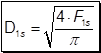
Diameter of the right branch (m) :
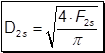
Diameter of the left branch (m) :
n Case of known left and right branch diameters
Cross-sectional area of the right branch (m²) :

Cross-sectional area of the left branch (m²) :

Cross-sectional area of the common branch (m²) :
![]()
Diameter of the common branch (m) :

Volume flow rate in the common branch (m³/s):
![]()
Mean velocity in the right branch (m/s):

Mean velocity in the left branch (m/s):

Mean velocity in the common branch (m/s):

Mass flow rate in the right branch (kg/s):
![]()
Mass flow rate in the left branch (kg/s):
![]()
Mass flow rate in the common branch (kg/s):
![]()
Reynolds number in the right branch:
![]()
Reynolds number in the left branch:
![]()
Reynolds number in the common branch:
![]()
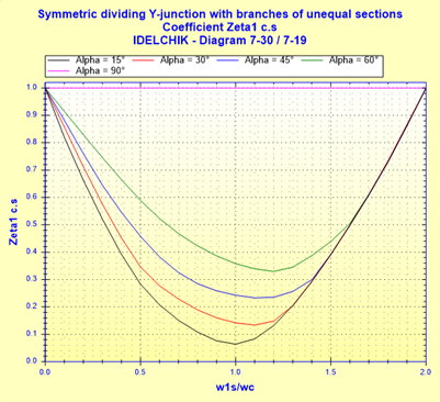
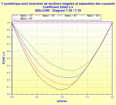
Pressure loss coefficient of the right branch (based on mean velocity in the common branch):
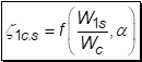 ([1]
diagram 7.30)
([1]
diagram 7.30)
Pressure loss coefficient of the left branch (based on mean velocity in the common branch):
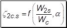 ([1]
diagramme 7.30)
([1]
diagramme 7.30)
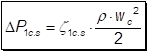
Pressure loss in the right branch (Pa):
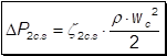
Pressure loss in the left branch (Pa):
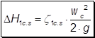
Head loss of fluid in the right branch (m):
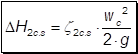
Head loss of fluid in the left branch (m):
Hydraulic power loss in the right branch (W):
![]()
Hydraulic power loss in the left branch (W):
![]()
Symbols, Definitions, SI Units:
a Half angle of the right and left branches (°)
Ds Diameter of the right and left branches (m)
Dc Diameter of the common branch (m)
F1s Cross-sectional area of the right branch (m²)
F2s Cross-sectional area of the left branch (m²)
Fc Cross-sectional area of the common branch (m²)
Q1s Volume flow rate in the right branch (m³/s)
w1s Mean velocity in the right branch (m/s)
Q2s Volume flow rate in the left branch (m³/s)
w2s Mean velocity in the left branch (m/s)
Qc Volume flow rate in the common branch (m³/s)
wc Mean velocity in the common branch (m/s)
G1s Mass flow rate in the right branch (kg/s)
G2s Mass flow rate in the left branch (kg/s)
Gc Mass flow rate in the common branch (kg/s)
Re1s Reynolds number in the right branch ()
Re2s Reynolds number in the left branch ()
Rec Reynolds number in the common branch ()
z1c.s Pressure loss coefficient of the right branch (based on mean velocity in the common branch) ()
z2c.s Pressure loss coefficient of the left branch (based on mean velocity in the common branch) ()
DP1s Pressure loss in the right branch (Pa)
DP2s Pressure loss in the left branch (Pa)
DH1s Head loss of fluid in the right branch (m)
DH2s Head loss of fluid in the left branch (m)
Wh1s Hydraulic power loss in the right branch (W)
Wh2s Hydraulic power loss in the left branch (W)
r Fluid density (kg/m³)
n Fluid kinematic viscosity (m²/s)
g Gravitational acceleration (m/s²)
Validity range:
· turbulent flow regime (Rec ³ 104)
· angle between the right and left branches between 30° and 180° (15° £ a £ 90°)
· common branch area equal to the sum of the areas of the right and left branches (Fc = F1s + F2s and F1s = F2s)
Example of application:
n Case of known common branch diameters
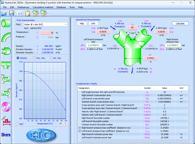
n Case of known left and right branch diameters

References:
[1] Handbook of Hydraulic Resistance, 3rd Edition, I.E. Idelchik
HydrauCalc Edition: June 2022
© François Corre 2022